9 Questions & 25 Answers
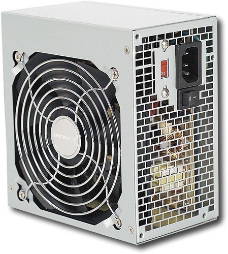
for Dynex™ - 520W ATX CPU Power Supply - Gray
>
>
>
Ask your questions. Share your answers.
 All
All All
AllQ:
the power supply in my hp pavilion desktop failed & i replaced it with this dynex 520 w ps. the ps works great, but now my computer won't boot up - windows won't start & i get a 'boot failure' message. what did i do wrong?by
Posted by:
dave w
from
santa fe nm
10 years, 3 months ago
Answers
A:
You probably forgot to connect your hard drive to the new power supply. Make sure it's fully seated.by
Posted by:
from
Honolulu
 read all my contributions
Additional information about EasyComp could not be loaded.
9 years, 1 month ago
A:
You forgot to plug in the 4 pin CPU power connector to the motherboard (some PCs even have 2 - 4pin CPU power connectors). Check all power connections and power on again.by
Posted by:
from
Colorado Springs, CO
read all my contributionsAdditional information about James could not be loaded.
9 years, 7 months ago
A:
Tough to say from that description, but, first thing to do is unplug the ac cable then all power connectors and reconnect them one at a time, starting with the 20 or 24 pin main-board connector and the cpu power connector that goes to the mb, then connect the hard drive power and if present the video card power. Now try to boot, if it boots then you can connect the rest of the power connectors after shutting down and unplugging the system. If not you may need professional help.by
Posted by:
from
San Antonio, TX
read all my contributionsAdditional information about CWST could not be loaded.
10 years, 1 month ago
A:
Most likely...the power cable to the HD is either installed backwards or not seated all the way. Make sure you have it installed correctly. I suggest you unplug the HD power cord (of course, disconnect the power supply altogether from the wall first), and re-seat it. Other possibility is that the motherboard power supply cable isn't seated all the way. Check both of those. Good luck!by
Posted by:
from
Baltimore, MD
read all my contributionsAdditional information about mchristino could not be loaded.
10 years, 1 month ago
A:
I would recommend bringing your HP Pavilion into a local store's Geek Squad, so they can take a look, and if necessary, ship off for service repair. It sounds like your computer needs service.by
Posted by:
read all my contributionsAdditional information about DynexCustomerSupport could not be loaded.
10 years, 2 months ago
Q:
How many SATA connectors, how many PCI connectors, in short, how many of what type does this power supply have? this should be in the full specs.by
Posted by:
Anonymous
10 years, 8 months ago
Answers
A:
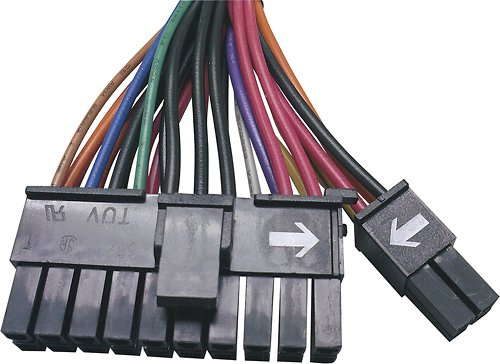
1 X 20+4 pin main power connector1 X 8 pin CPU connector (4+4 so can be used where only one 4 pin connector is needed)
3 X IDE connectors
4 X SATA connectors
1 X floppy connector
1 X 8 pin PCIE connector (6+2 so can be used as a 6 pin connector) I believe 520 watts is peak power so don't plan on powering a high end graphics card though
by
Posted by:
read all my contributionsAdditional information about kansasnoob could not be loaded.
6 years, 3 months ago
A:
1- 24 pin main connector 20+4,3- 4 pin connectors for 5.25 drives
4- SATA connectors
1- 8 pin 12V 4+4 CPU power connector
1- 6 pin PCI express 2x3 power connector
1- 8 pin 2x4 PCI express (6+2) power connector
1- floppy drive connector
cable length is 15.75 in
by
Posted by:
Acarpenter
6 years, 5 months ago
A:
1 PCI-E 5x sata 2x molex 1x floppy 1x 4pin 1x 20+4by
Posted by:
from
Peoria IL
read all my contributionsAdditional information about DZII could not be loaded.
9 years, 10 months ago
A:
In the User Manual (found in the Support/Downloads tab), of this page: http://www.dynexproducts.com/products/computer-accessories/DX-520WPS.html, it states that the wire configuration is as follows:20+4 PIN Main Power Connector (1): Connect to motherboard
8 PIN (4+4)+12V Processor Connector (1): Connect to the motherboard for the CPU.
4 PIN Peripheral Connector (3): Connect to the internal IDE drives
Serial ATA Connector (4): Connect to the internal SATA drives
8 PIN PCI-E Connector (1): Connect to the PCI-E graphic card that requires power.
6 PIN PCI-E Connector (1): Connect to a PCI-E graphic card that requires power
Floppy Drive Connector (1): Connect to the 3.25” floppy drive.
by
Posted by:
read all my contributionsAdditional information about DynexCustomerSupport could not be loaded.
10 years, 7 months ago
Q:
I just replaced my power supply on my desktop is a Amd quad core with a Sata drive msi motherboard. After putting the power supply in, it didn't work right away. I rechecked and replugged power to motherboard and waited. After a few minutes it went on. It works fine now, but if I power off my tower and shut off my power surge it doesn't power up again. Then I have to open the tower again and wait few minutes. Do I have a defect power supply or does the computer have to stay on all the time?I just purchased at best buy 2 day ago?
by
Posted by:
Kmd
from
Paramus
10 years, 2 months ago
Answers
A:
Sounds like it may be defective but you need to figure out why the old power supply failed - or did it fail? It wouldn't make sense to have to leave it powered up all the time.by
Posted by:
read all my contributionsAdditional information about kansasnoob could not be loaded.
6 years, 3 months ago
A:
Check that you connected the 4 pin CPU power cable to the mother board.by
Posted by:
from
Colorado Springs, CO
read all my contributionsAdditional information about James could not be loaded.
9 years, 7 months ago
A:
I have had no issues like that but it sounds more like something is discharging the capacitors on the motherboard which would cause a delay because it has to recharge the board before it can power up. That is lime 30-40 seconds usually.by
Posted by:
from
Hastings, Mi
read all my contributionsAdditional information about Ron420 could not be loaded.
10 years ago
A:
That sounds like a defective part. You should be able to return, or exchange the item within 15 days of purchase with no restocking fee.10 years, 2 months ago
Q:
A while ago I upgraded my dell dimension e520 from a intel dual core 1.83 Ghz to an intel pentium d 930 3.00 Ghz cpu. However, the model compatibility states that it works with dual-core and multicore CPUs. Would it still work with the cpu I currently have?by
Posted by:
Jon
from
Springfield, IL
9 years, 1 month ago
Answers
A:
Yes, it should work fine.by
Posted by:
read all my contributionsAdditional information about kansasnoob could not be loaded.
6 years, 3 months ago
A:
Yes, this power supply will work with Intel and AMD multi-core processors like the ones you mentioned.9 years, 1 month ago
A:
Of course it will work, but you might want to go with the Thermaltake brand instead. Their 430-watt would be sufficient and it's around the same price.by
Posted by:
from
Honolulu
read all my contributionsAdditional information about EasyComp could not be loaded.
9 years, 1 month ago
Q:
Can this unit power a PNY Nvidia GTX 550 Ti, at high speed?by
Posted by:
Anonymous
11 years, 9 months ago
Answers
A:
I would go with something with a little higher continuous power rating. The continuous rating on this is around 440 watts. I'm too lazy to take the side cover off my system to check it right now, but in my Gigabyte P43 system I have a 650 watt continuous supply. The quad-core Intel CPU uses 130 watts by itself.John
by
Posted by:
from
Annapolis, MD
read all my contributionsAdditional information about Oldradioguy could not be loaded.
9 years, 3 months ago
A:
Peak is 22 AMPsby
Posted by:
from
Colorado Springs, CO
read all my contributionsAdditional information about James could not be loaded.
9 years, 7 months ago
A:
I am running it on a NVIDIA 660 GTX with no issues.by
Posted by:
Novulo
from
Charlotte, NC
10 years, 9 months ago
by
Posted by:
kablekat
6 years, 5 months ago
Answers
A:
I would think soby
Posted by:
Acarpenter
6 years, 5 months ago
A:
yes it is a great power supplyby
Posted by:
Acarpenter
6 years, 5 months ago
Q:
Does this power supply come with all connectors so that I can just plug and play with my dell dimension e520 desktop? or do I need to purchase more connectors?by
Posted by:
camar0guy
from
ohio
10 years, 9 months ago
Answers
A:
Yes, any psu will pretty much plug and play with almost all standard pc's. I would highly recommend the Corsair 700 watt modular psu....it comes with all the cords needed and then some extra if you ever upgrade your pc....all for about $90Products from my answer

Corsair - RM Series RM750 750 Watt 80 PLUS Certified Fully Modular PSU
by
Posted by:
from
Cincinnati
read all my contributionsAdditional information about Hazy101 could not be loaded.
9 years, 8 months ago
A:
You should not have to purchase any more connectors to use your Dell Dimension E520. In the User Manual (found in the Support/Downloads tab), of this page: http://www.dynexproducts.com/products/computer-accessories/DX-520WPS.html, it states that the wire configuration is as follows: 20+4 PIN Main Power Connector (1): Connect to motherboard 8 PIN (4+4)+12V Processor Connector (1): Connect to the motherboard for the CPU. 4 PIN Peripheral Connector (3): Connect to the internal IDE drives Serial ATA Connector (4): Connect to the internal SATA drives 8 PIN PCI-E Connector (1): Connect to the PCI-E graphic card that requires power. 6 PIN PCI-E Connector (1): Connect to a PCI-E graphic card that requires power Floppy Drive Connector (1): Connect to the 3.25” floppy drive.by
Posted by:
read all my contributionsAdditional information about DynexCustomerSupport could not be loaded.
10 years, 7 months ago
Q:
I need to replace my psu in the dell inspiron 521s modelby
Posted by:
Anonymous
11 years, 2 months ago
Answers
A:
I believe the tower takes a standard power supply so close to anything should work. If anything take the unit to Geek Squad and an Agent can take a look for you. I would like to also mention if you have not changed anything on the unit your watt requirement should still be on the power supply you have in the tower.Products from my answer
Dynex™ - 520W ATX CPU Power Supply - Gray
 (106)
(106)
Dynex™ - 400-Watt ATX CPU Power Supply - White
(247)by
Posted by:
from
Covina, CA
read all my contributionsAdditional information about AgentE could not be loaded.
9 years, 8 months ago
A:
This fits in my Inspiron 530. It was the same size as the default power supply so I would think it should fit.by
Posted by:
Novulo
from
Charlotte, NC
10 years, 9 months ago
by
Posted by:
Greg
7 years, 7 months ago
- 2024-05-01 T01:21:42.517-05:00
- bvseo_pps, prod_bvqa, vn_prr_5.6
- cp-1, bvpage1
- co_hasquestionsanswers
- loc_en_US, sid_2658156, prod, sort_helpfula
1 of 1
Best Buy is not responsible for answers provided by Community Answers, Customers, or other third parties. Accuracy not guaranteed.